How to Select a Rotary Airlock/Feeder Valve for Your Powder Processing Needs
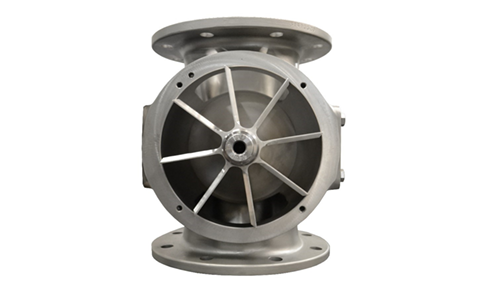
For bulk powder processing plants, rotary valves — also known as rotary airlocks, rotary feeders, and countless other variations — control the flow of powder into and out of many critical points within the plant. Beyond controlling the flow of powder, rotary valves can be vital for safety as they often act as a flame barrier and process isolator in the event of a dangerous dust explosion.
Because rotary valves are important safety and efficiency mechanisms, selecting a high quality rotary valve that fits your system is a crucial task. And with varying customizations in terms of type, size, material, function, and more, it can be hard to know which direction to take.
To help you select the best rotary valve for your powder processing plant, we’ve outlined the things you need to know before starting your search.
1. Type
First and foremost when adding a rotary valve to your system, you need to make sure the new component is the right type for the function it will be serving. There are two basic types of rotary valves.
- Drop through, where product feeds into an inlet on the top and drops out of the outlet below.
- Convey through (sometimes called blowing seals) where product feeds into the inlet and is directly fed into a pneumatic convey line connecting to ports on the bottom sides of the housing end covers.
There are many variations of valves within these two main types. Determine the type you need by starting with what function the rotary valve is serving.
- Airlocks separate the pressure differentials on the inlet and outlet side of the valve while allowing product to flow between, much like a revolving door separates the temperature differentials on the inside and outside of a building while allowing people through. Product flow rate though the valve is not a big determining factor in selection, and the valve may be much larger than required for the rate to prevent product bridging and backup. Typical applications include cyclone and baghouse outlets.
- Feeders control the rate at which product feeds through the valve by turning the rotor at a set speed precisely metering the flow of the bulk powder material. These valves are used in application where pressure differential is low or nonexistent such as gravity feed chutes from storage silos and feeding powder into packaging machines.
- Airlock feeders combine the two functions together to create a diverse, multi-functional valve. These applications include feeding powder into pneumatic conveyors or feeding product out of pressure and vacuum receivers.
Drop through rotary valves can fit all of the above three functions while convey through are only suited to applications were the valve is directly feeding a pneumatic conveyor. The convey through option may provide also a more efficient option where height of the equipment is limited.
Other key factors to consider that will affect the specific type of valve you need are:
- Materials of Construction. The materials of the housing, rotor, drive, and any accessories should be selected to match the requirements of the product and surrounding area. Especially when the valve is located outdoors, in a wash down environment, or when hygienic construction is required.
- Ease of Cleaning. If your process and product require frequent cleaning it is important to select a valve designed for this kind of use. Most low-cost rotary valves are built to only be taken apart for major maintenance such as bearing replacement. These valves do not facilitate easy access to product contact surfaces for cleaning. Select a valve that is designed to be easily demountable with supports for heavy parts such as rotors and endplates. In dairy, pharmaceutical, and other hygienic applications assure the valve is designed with surface finish, seals and construction that are cleanable and meet regulatory standards such as USDA and EHEDG. A large rotary airlock not designed properly can turn cleaning into a tedious, dangerous and time-consuming task.
- Explosion protection. If the location requires explosion isolation make sure the valve is designed to meet NFPA or ATEX requirements as needed.
2. Size
Once you know the type of rotary valve required the next step is to determine the size needed. Consider these two items to determine rotary valve size:
- Volumetric capacity. Rotary valves that are controlling the feed rate of product are sized by the volumetric capacity of one revolution of the rotor (swept volume). This is typically measured in cubic feet or liters. A simple formula can be used to determine the required valve capacity:
C = R / D / E / S
Where C = Required Swept Volume Capacity
R = Convey Rate (units/minute)
D = Product Density
E = Valve efficiency (decimal percentage)
S = Rotor speed (rpm)
Example: A rotary valve feeding 100 lbs./min of milk powder with a bulk density of 35 lbs./cu. ft.
- Rotary valves typically run with efficiencies ranging between 65-85%. Product followability, pressure differential, type of feed to the valve, and rotor design can all affect this. For this instance, let’s estimate a 70% efficiency.
- To determine rotor speed, we need to select a speed that is at the higher end of the valve’s capable range within the efficiency we estimated.
- The limiting factor of this speed is how quick the rotor can spin while still allowing product to fill the rotor pockets at an efficient rate. For most valves under 16” in flange size this is in the 25-30 rpm range.
- So, for this application C=100/35/0.7/25 or 0.163 cu. ft./revolution. You should select a valve with a swept volume at least this large and run the rotor at a speed that will meet the required convey rate.
- Flange size. The other determining factor in selecting rotary valve size is the size of the mating flange the valve is connecting to. You do not want the rotary valve to be a restriction that may lead to product bridging or backup. In applications where the rotary valve is acting as just an airlock, where product feed is not metered by the valve, the flange and inlet opening size should override volumetric capacity in your selection.
3. Characteristics of the Product & Solutions
The product that is being transported and any cleaning solutions the valve is exposed to will impact many aspects of the rotary valve. In depth experience is required to know how different products will affect rotary valve performance, and what combinations of modifications, option, and accessories may be required to deal with any problematic applications. Have this historical information ready before you start your search and be sure to make your manufacturer and sales representatives aware to avoid any pitfalls in valve performance down the road.
4. Pressure
Depending on the pressure of your conveying system, you may need a feeder that is built more durable. For example, dilute phase pneumatic conveying systems typically operate between 4 and 8 PSI (pounds per square inch) versus dense phase pneumatic conveyors, which usually operate over 15 PSI. Environments with high pressure or vacuum will need a more durable rotary airlock feeder designed for this higher pressure. High pressures may also require the addition of venting systems to prevent the air leakage from interrupting product flow into the valve. Applications that need to withstand a pressure shock wave from an explosion may also require a more robust rotor and housing design.
5. Temperature
Extreme high or low temperature applications may limit the material of construction, rotor design, and airlock capabilities of the valve. Below freezing temperatures and temperatures over ambient may require modifications to drive motors, rotor construction, seals, bearings and many other aspects of the valve design. Know your product and air temperatures around the rotary valve before you begin your search.
Interested in discussing rotary valves? Fill in your information below and a representative from PPS will connect with you within one business day!


